 Focal Quality and Point Spread Function Simulation
- Technique Comparison
- Intelligent Alerts About Inspection Quality Issues (Warnings)
- Dynamic Workspace Information
- NDT Axes
- Expanded Support for Simulation/Visualizations in Custom Pieces
- Automatic Highlighting/Fading of Active/Inactive Beams & Probes
- New Probe Type
- FMC Beamset
- A-Scan Simulator
- Data Import
- PipeWIZARD Support Changes
- New Piece Types
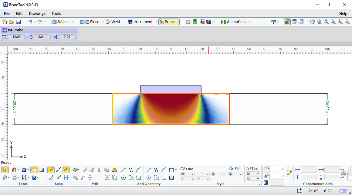
- Advanced FMC/TFM Focal Quality Map
- Built In Simulation
- New Report Editor
- Angle Inspector
- Auto Cal Block
- Square Caps
- Wedge Gap Drawing
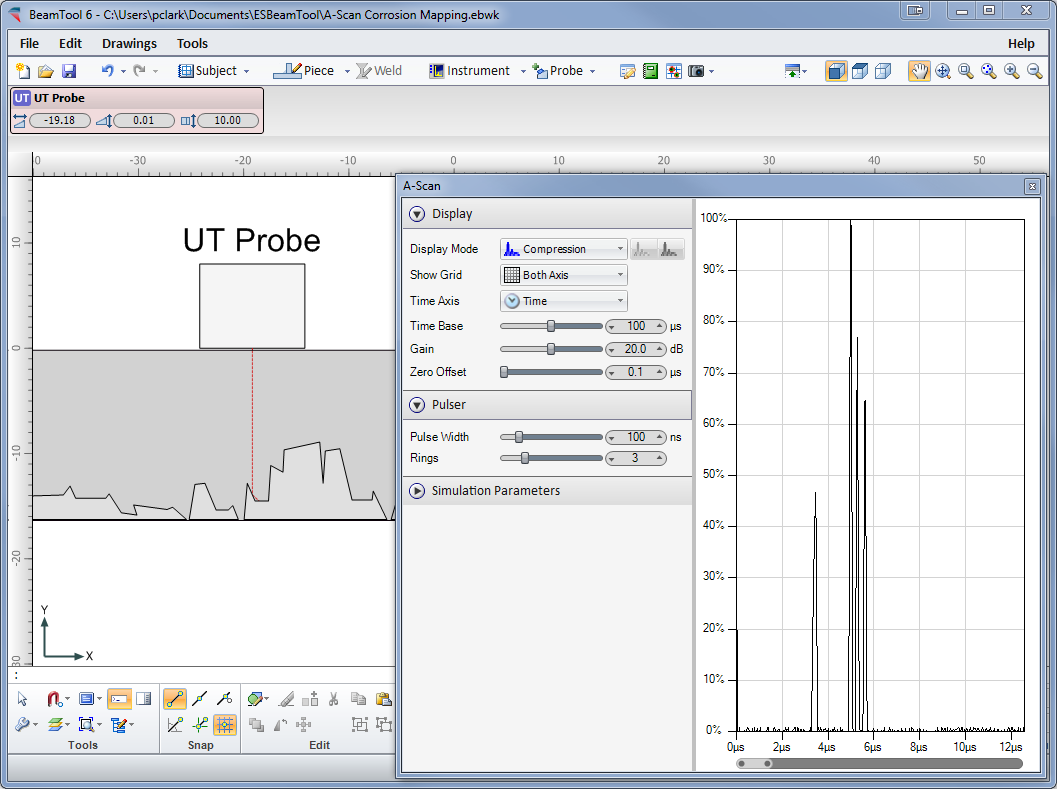
- Improved A-Scan Simulation
- Additional Animation Options
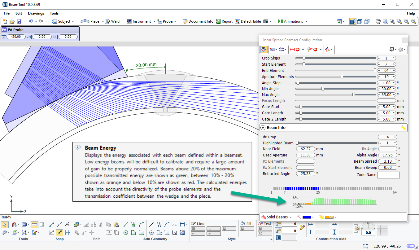
- New Beam Energy Plot
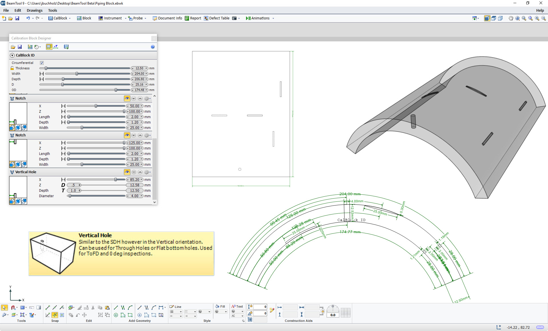
- Curved Calibration Blocks & Vertical Holes
- FMC Beamset Validation
- NDT Data Import & Data Folding
- Sectorial Beamset Beam Energy Display
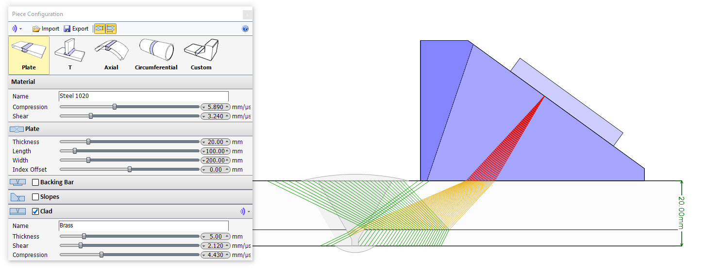
- Clad Layer Inset
- Spline CAD Support
- AOD & COD Wedge Curvature
- DLA & DMA Probes with
Focal Law Export - Beam Highlighting & Focal Law Delay Visualization
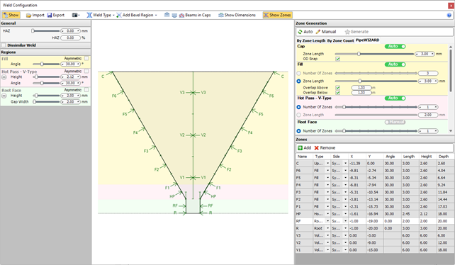
- Asymmetrical Welds
- Clad Material Support
- Transverse Probes
- Improved CAD Tools
- Sound Mode Colorization
- Compound S-Scan
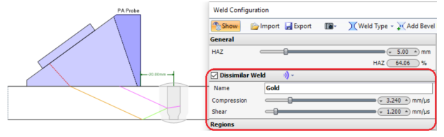
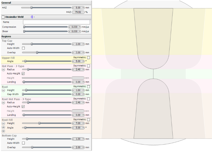
- Dissimilar Weld Material
- 3D Sound Paths Ray-tracer
- Inset Backing Bar
- Custom Velocity Modes with Path Cropping
- Double J Welds
- Transverse Angle Measurements
- Additional High Temp Wedges
- Phased Array
- Conventional UT
- TOFD
- Export Focal Laws
- T Piece Configuration
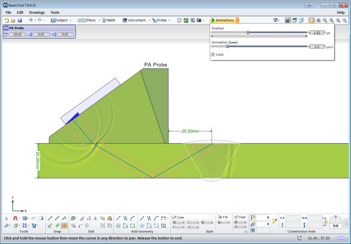
- Sound Propagation Animation
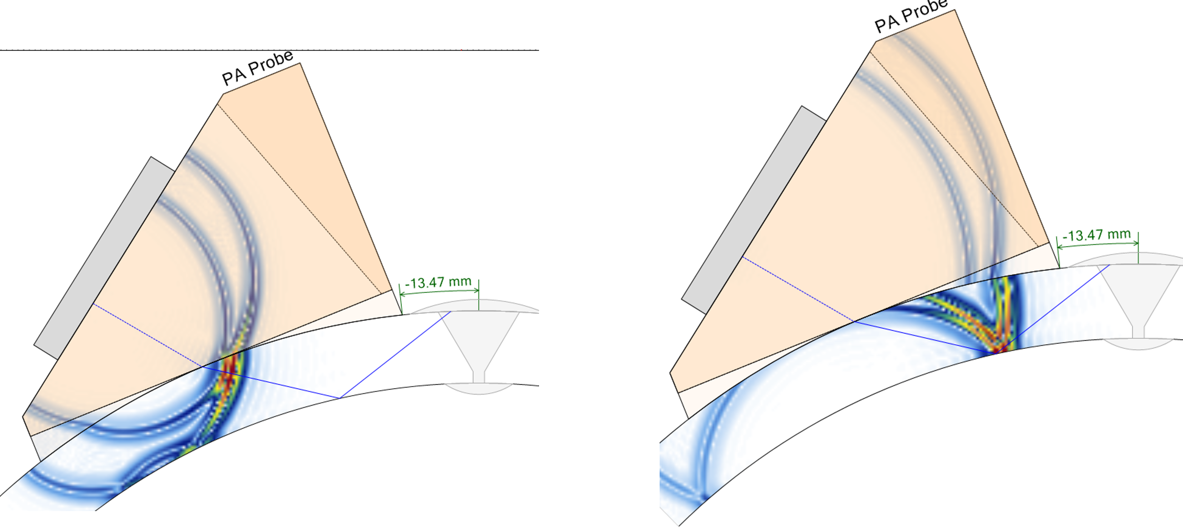
- Sound Pressure Visualization
- Indication Drawing Set
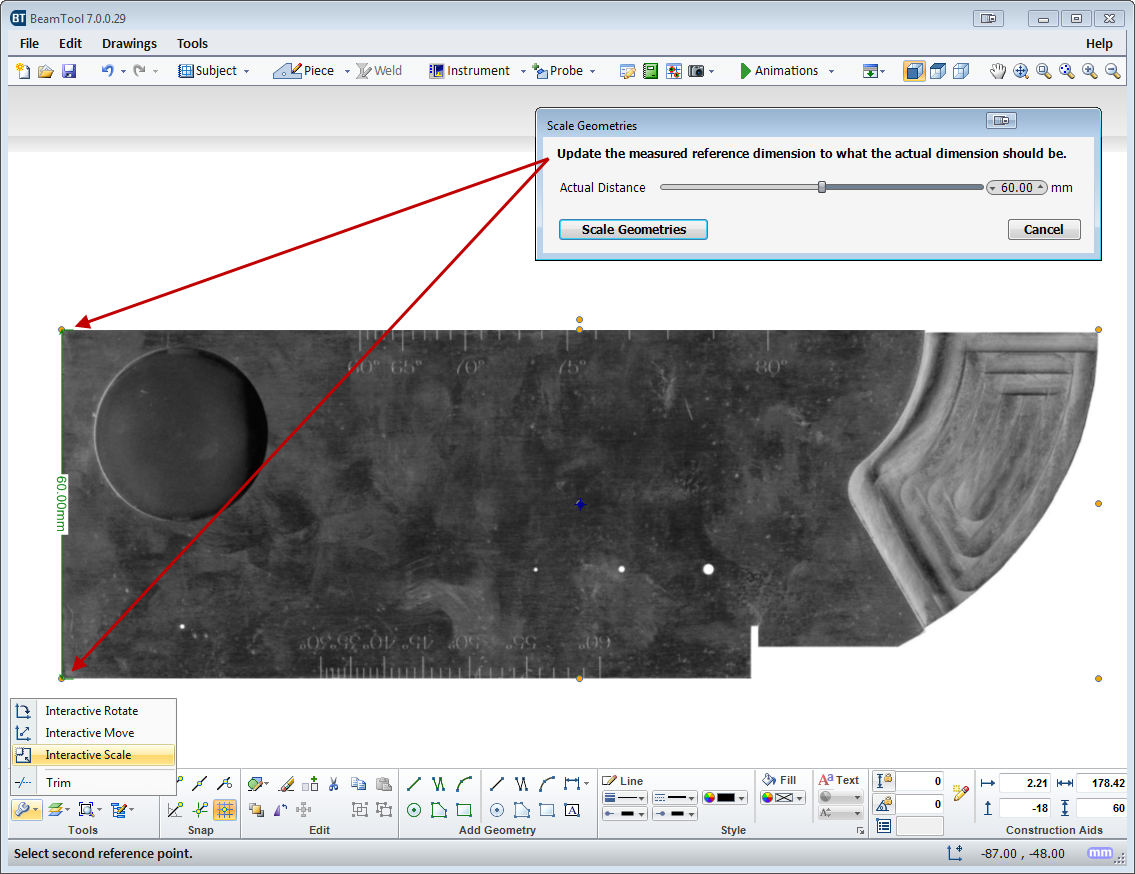
- Interactive Scale
- Wavelet Visualization
- 3D Rendering of
Circumferential Piece - Add Indication from Geometry
- Beam Crop Modes
- Multi-Discipline Technique Development
- 3D Workspace View
- CAD Functionality
- Piece Configuration
- Weld Configuration
- Bitmap Backdrops
- Defect/Indication Plotting
- Configurable Reporting
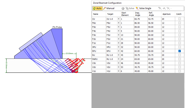
- Zonal Discrimination
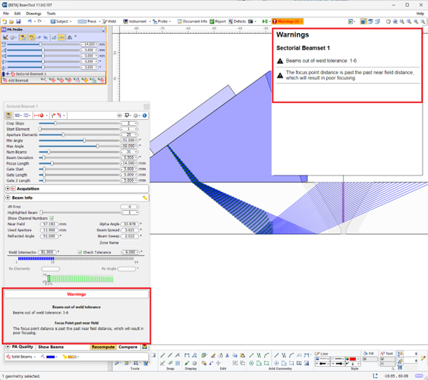
- Using beams with low beam quality (eg. low transmitted amplitude)
- Specifying a focus which is beyond the effective nearfield for the array (focusing not possible)
- Setting a passive aperture larger than active aperture (affects near field approximations)
- Discrepancy between the wedge angle & piece surface angle (if they do not match)
- Beams intersect the weld at an angle that is outside of a configurable tolerance
- Attempting to use shear sound mode with a contact probe
- Beams do not enter the piece (eg. they intersect the damper or cannot be computed)
- Velocity mismatch between configured velocity and custom geometries
- Probe/Wedge parameters differ from the catalog values
- Weld contains cap but caps are ignored for relections
- Incorrectly configuring the instrument (eg. Number of available law channels)
- Cal block shape/piece parameters do not match
- Cal block is not large enough to fit auto-targets
- Custom geometry is improperly drawn (eg. self intersecting, zero length segments, etc...)
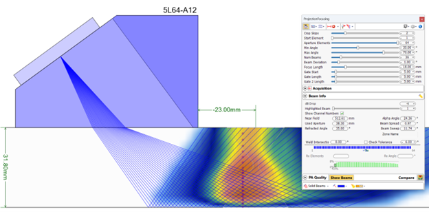
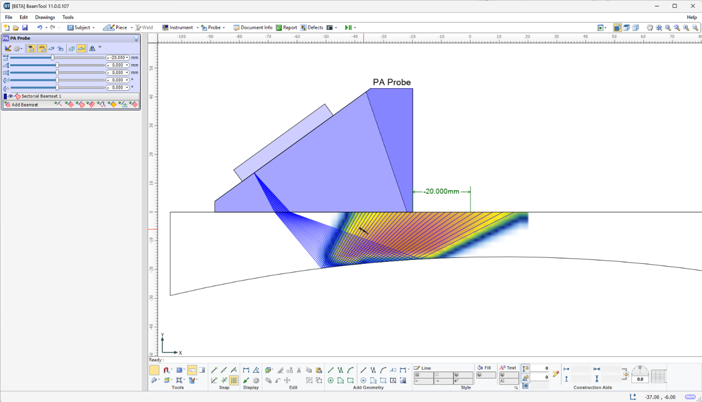
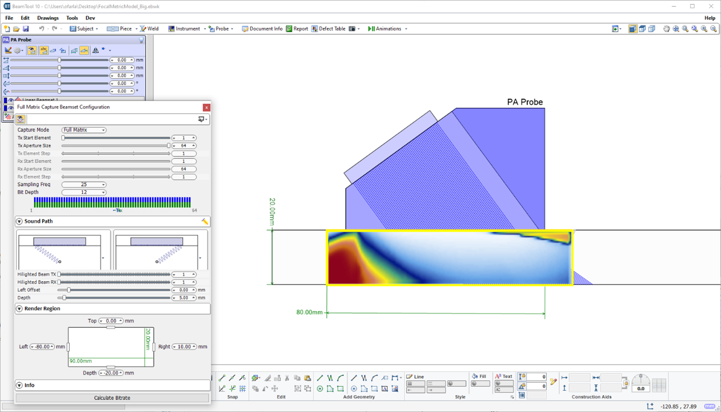
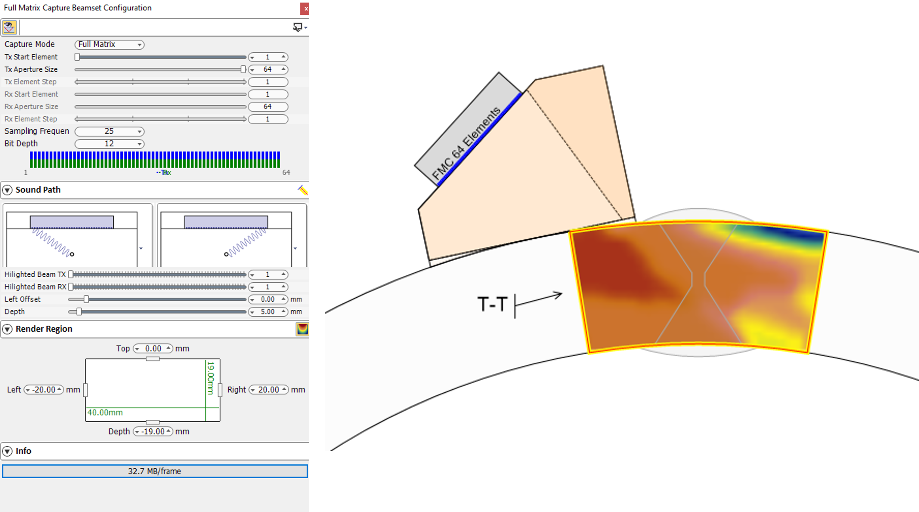
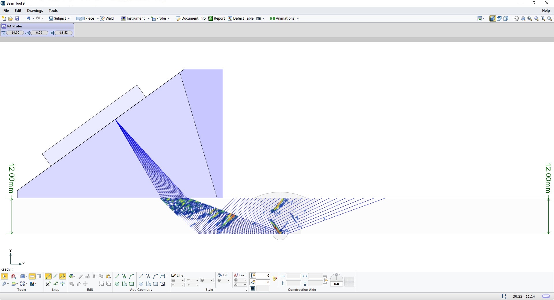
Focal Quality and Point Spread Function simulation were introduced in BeamTool10 as a means of assessing the spatial sensitivity and resolution of FMC/TFM techniques. In BeamTool 11 these features have been improved and expanded to support Phased Array beamsets as well. The focal quality simulation allows the user to quickly visualize how the amplitude, shape and size of a point reflector (small side drilled hole) varies throughout the inspection region for a given technique. The user can use this information to select the appropriate essential technique parameters (aperture, focusing, index offset, etc.). Several focal quality metrics derived from the “Point Spread Function (PSF)” can be overlaid on the piece and their precise numerical values read at any given mouse position allowing for direct estimation of target resolution and sizing accuracy.
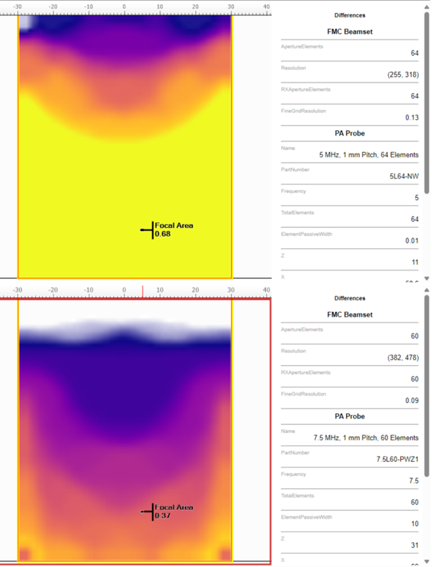
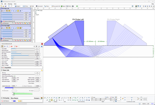
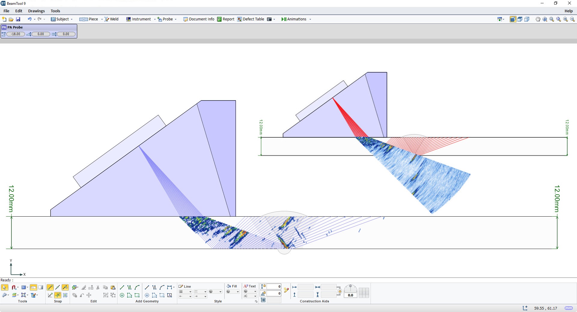
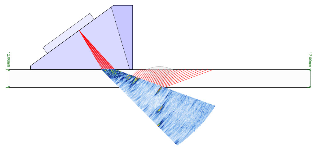
New in BeamTool 11 is the ability to quantitatively compare candidate inspection techniques (supported for FMC, Linear, Sectorial and Spread Beamsets). Beamsets generated with different probes (frequency, pitch, wedge parameters), apertures, focusing type (true depth, half path, unfocused) scan type (linear, sectorial, spread/compound) can be selected for comparison and appear in a split-screen view. Focal quality metrics associated with each technique are overlaid on the piece with a consistent palette to facilitate discriminating between them. The point spread function simulation and corresponding focal metrics (sensitivity, focal area, vertical resolution, horizontal resolution, lateral resolution, axial resolution) are displayed independently for each technique for ease of comparison.
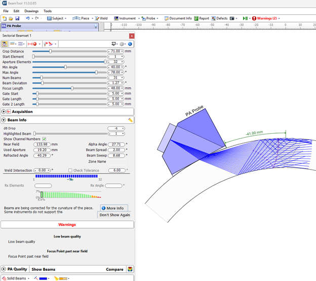
In BeamTool 11 the user is alerted to potential issues with the selected technique by a “Warnings” tab. Technique pitfalls to which the user will be alerted to in the “Warning” tab include:
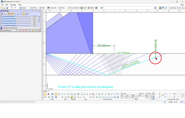
A new “Workspace Information” option has been added in BeamTool 11 which when enabled, provides the user information about the beam nearest to the mouse position – this information includes travel path, time of flight, beam angle, etc.
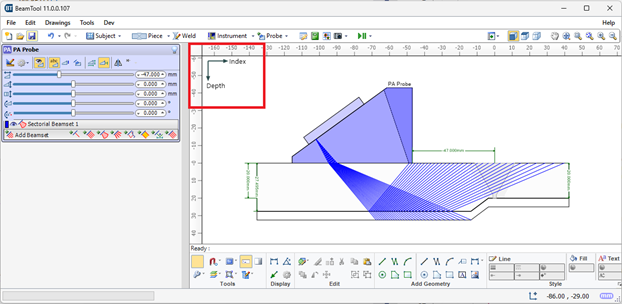
In response to popular demand, the option to change the coordinate system from the default global Cartesian coordinate system (x,y,z) to the NDT industry standard coordinate system (Index, Depth, Scan) is available in BeamTool 11. When the NDT axes are employed, all pertinent geometric information is labeled with respect to the Index, Depth, Scan axes which may facilitate reporting/technique documentation.
In BeamTool 11 the user can now use any of the Point Spread Function/Focal Metric simulation features in custom work pieces (previously only supported in standard pieces). The user may use the CAD tools to represent arbitrary inspection geometries and then select the appropriate component surfaces as the front and back walls of the piece.
To facilitate workspace navigation, the probe/beamset closest to the user’s mouse position in the probe/beamset list is automatically highlighted.
New Probe Type: Transverse Conventional.
New quality metrics including point spread function preview and more parameters.
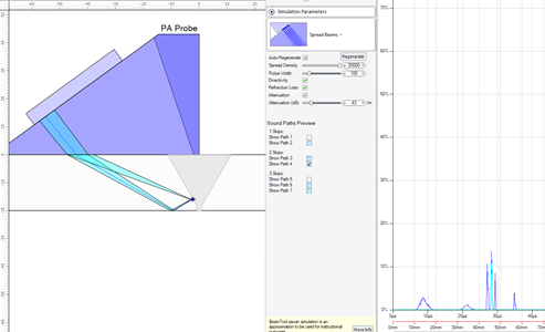
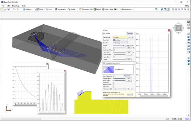
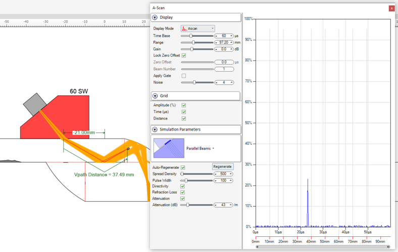
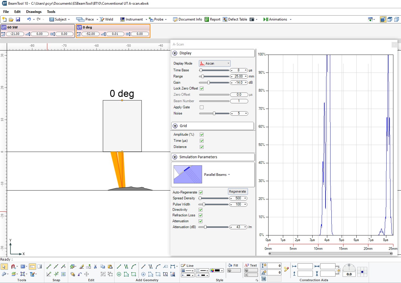
A-Scan Simulator can now show the travel paths that form the A-scan response.
BeamTool now supports importing MX2.odat files.
New zone configuration interface, ability to solve for Cal block targets instead of Zones, and improved integration between Zonal Cal block and Zonal Beamset.
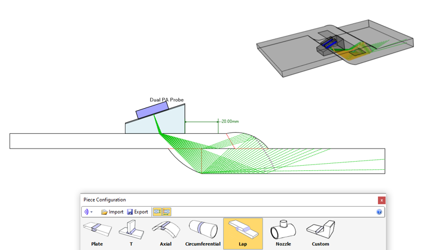
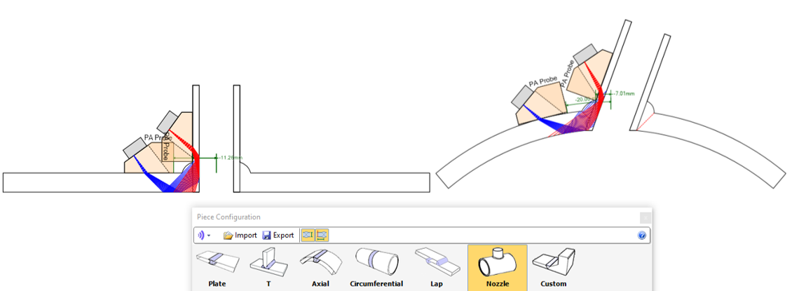
Two new Piece Templates have been added to BeamTool, a Lap Joint and a Nozzle weld. The Lap joint has the same configuration as a Plate plus controls for overlap and weld configuration. The Nozzle is 2 dimensions but you can toggle between a 0 degree aspect and 90 degrees, representing the minimum and maximum deflections found in the weld profiles.

Advanced FMC/TFM Focal Quality Map.
The Simulation features previously separate from BeamTool are now included when upgrading to or purchasing BeamTool 11! Great as a training aid or for generating training material and conveying principles.

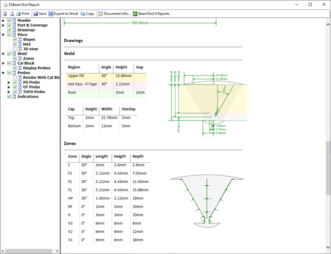
The report editor has been rebuilt to allow easier configuration of the report contents. More options have been added as well including 3D views, drawing sets, and Calibration Block. The provided templates from previous versions as well as User designed ones can still be utilized.
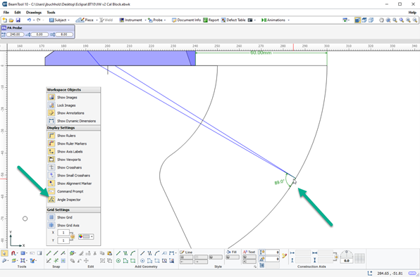
Hover over intersecting lines with the Angle Inspector on, and the angle will be displayed overlaid on the workspace.
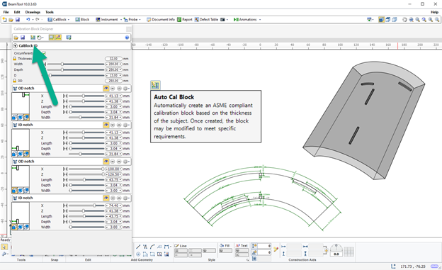
The Standard Calibration Block feature now supports “Auto Cal Block” for curved pieces. Selecting this will create an ASME compliant block based on the thickness specified, adding notches and SDH’s. You can further modify to meet your specific need.
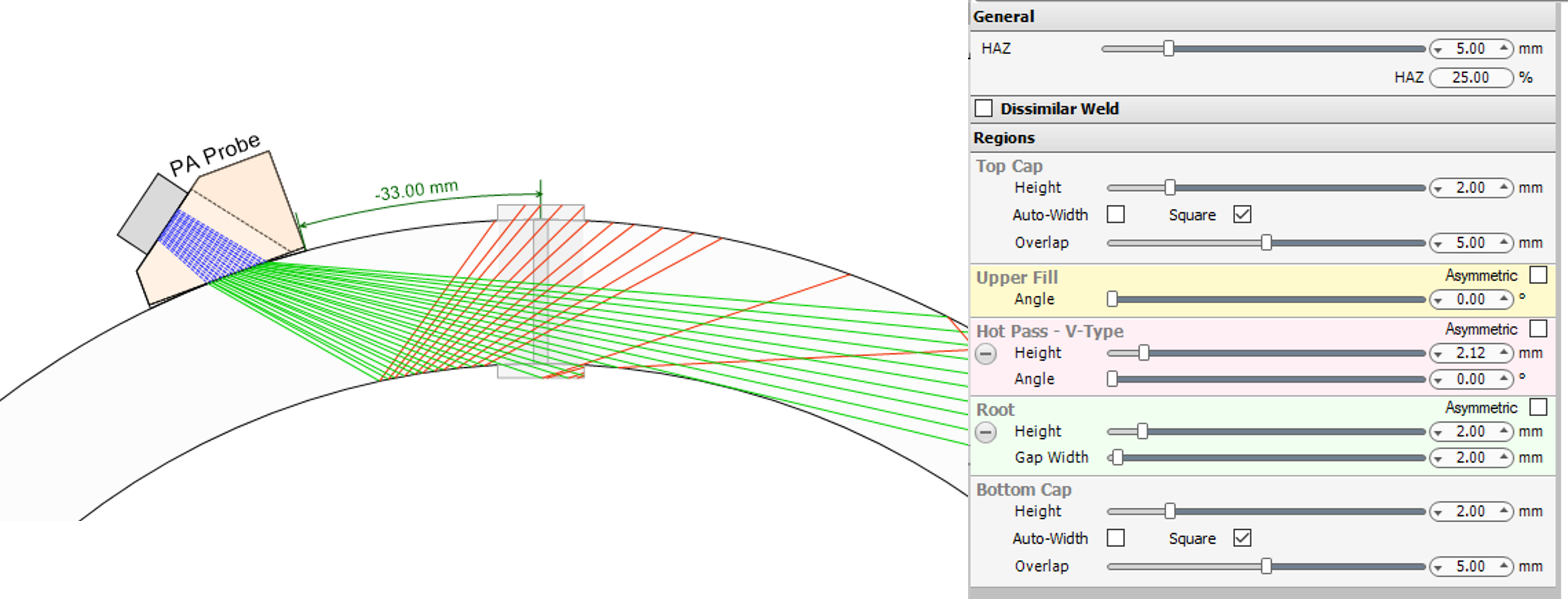
Welds can now be configured to have square caps, simulating ERW welds with the upset material removed.

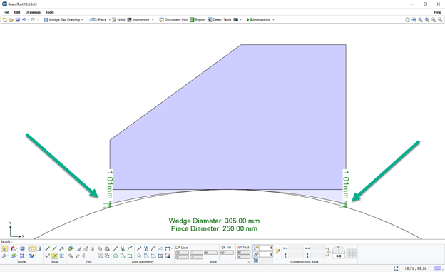
A Wedge Gap drawing can be generated that will show the dimension of any gap between the wedge and the piece due to a mismatch in profiles.
Improved A-Scan Simulation.
Additional Animation Options.
The Beamset Beam Energy Plot has been updated and refined to display the maximum possible transmitted energy more accurately.
Piping or Curved Calibration Blocks are now supported in the standard calibration block designer included with BeamTool 11. Add notches in the circumferential plane and the curvature will be respected. Generate drawings that can be supplied to a machine shop. Vertical FBH’s and Through Holes are now supported for both flat and curved calibration blocks.
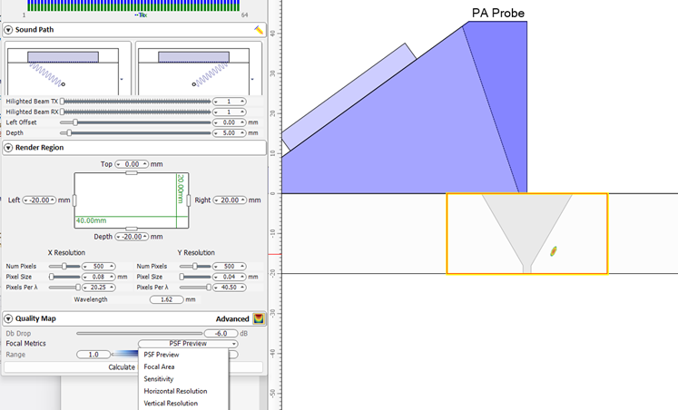
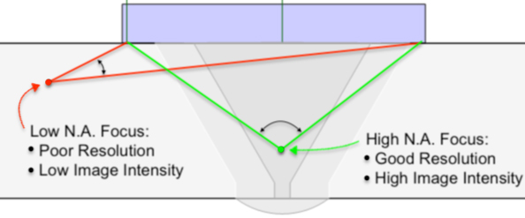
BeamTool can help you choose an appropriate rendering region for an FMC inspections (currently only available for contact FMC inspections) by plotting a Quality Map, which roughly quantifies the resolution and image intensity of reflectors positioned with respect to the probe aperture. This map roughly quantifies the quality of focus for each pixel point in the chosen rendering region by computing the effective "Numerical Aperture", defined as sine of half of the angle between the first and last beams covering the pixel.
The concept of numerical aperture comes from microscopy and represents the angular coverage of a focal point. A low numerical aperture value implies that energy is not effectively focused at a particular point leading to poor resolution and low image intensity, whereas a high numerical aperture value means that energy is highly focused leading to high resolution and high image intensity.

BeamTool has the ability to import supported NDT data directly into the workspace! View and scroll through the data either as is, or folded along the soundpath. Apply an Alpha Threshold to the data to remove noise and low amplitude signals. The Olympus NDT data Access Library is required to do this and can be download from their site by following this link:
NDT Data Access Library 32bit (for BeamTool 9)
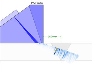
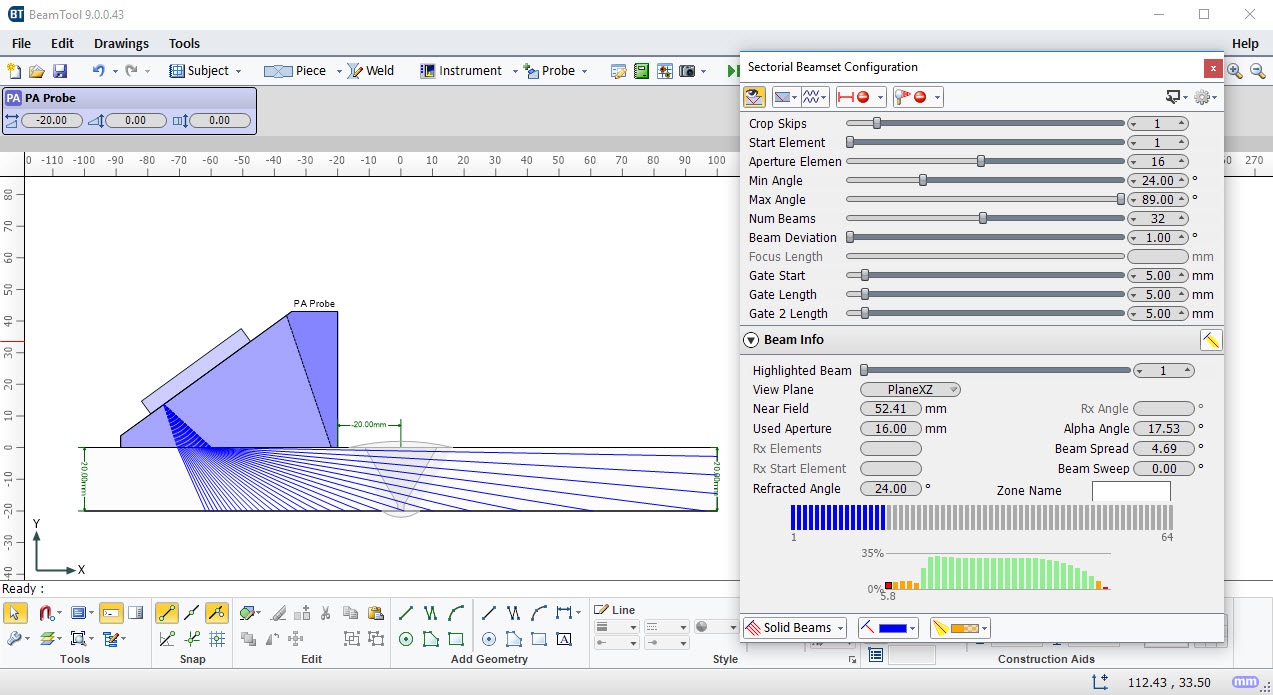
BeamTool now helps you to select the correct range of angles for Phased Array inspections by displaying the energy associated with each beam defined within a beamset. Low energy beams will be difficult to calibrate and require a large amount of gain to be properly normalized. Beams above 50% of the maximum possible transmitted energy are shown as green, between 10% - 50% shown as orange and below 10% are shown as red. The calculated energies take into account the directivity of the probe elements, the transmission coefficient between the wedge and the piece, as well as the reflection coefficients for each skip within the piece.
The Clad Layer in BeamTool is now Inset so that it is drawn in line with the weld bevel.
BeamTool can now import CAD drawings with Splines.
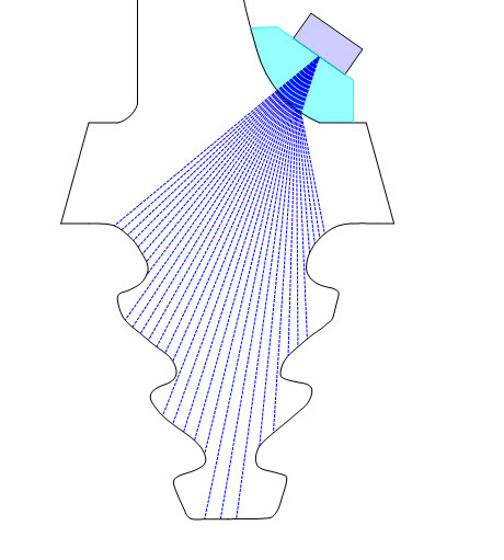
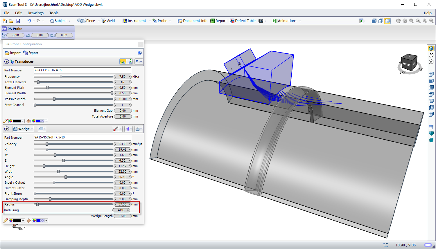
AOD and COD profiled wedges can now be configured and pinned to your Circumferential and Axial Pieces.
BeamTool now supports Dual Phased Array probes.
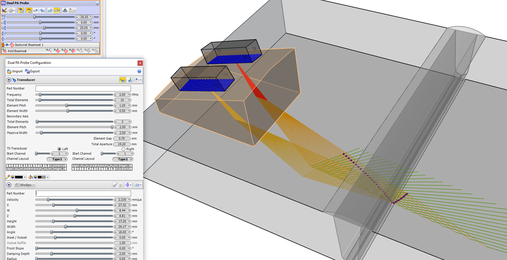
For multi-beam beamsets, you can highlight a single beam and also view its focal law delays.
Weld region parameters can be separately configured for the left and right side of the weld bevel.

A clad layer can now be added to a plate, T, axial or circumferential piece configuration.

BeamTool now supports the rotation of probes around the vertical axis.
Indications/defects can be moved and resized by dragging them on the canvas.
When both compression and shear paths are displayed, you can now color each sound mode independently.
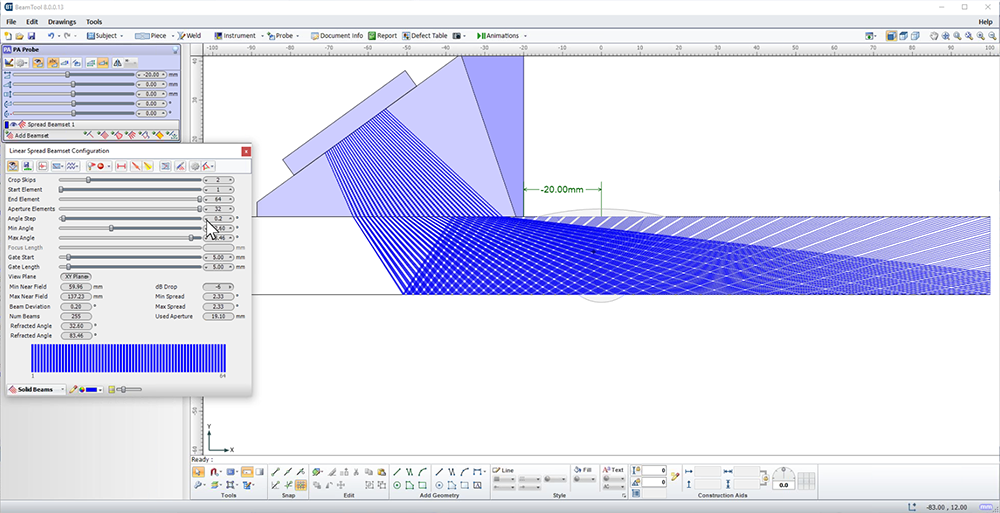
The Linear Spread beamset now supports Compound-S mode which allows specifying the angle step between each successive beam.
The weld can now be a different material than the rest of the piece. For the sound paths to be affected by the alternate material, "Reflect off Weld" must be chosen in the Beamset configuration.
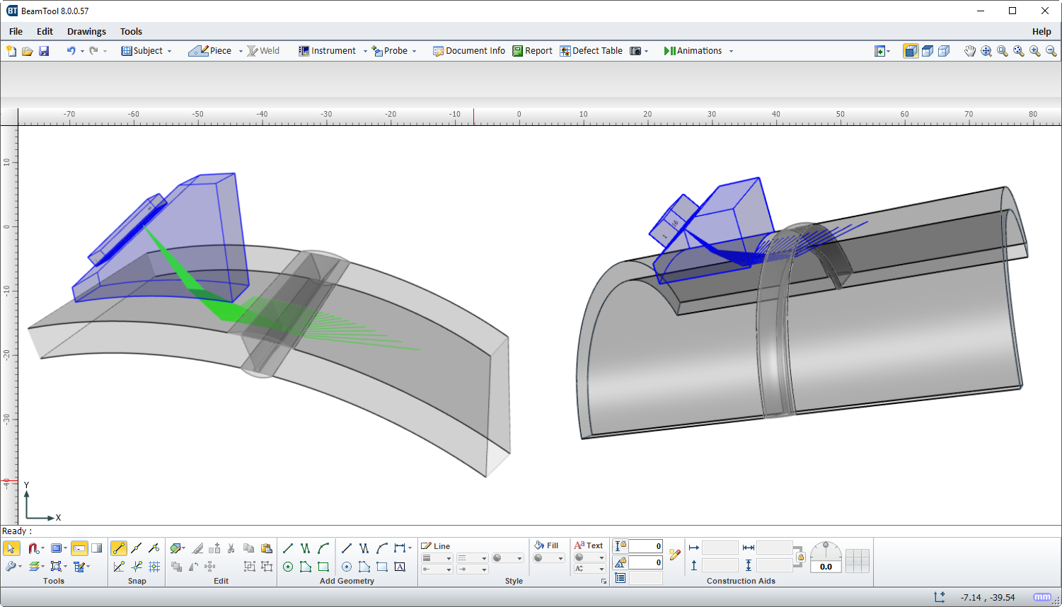
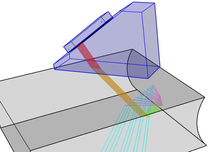
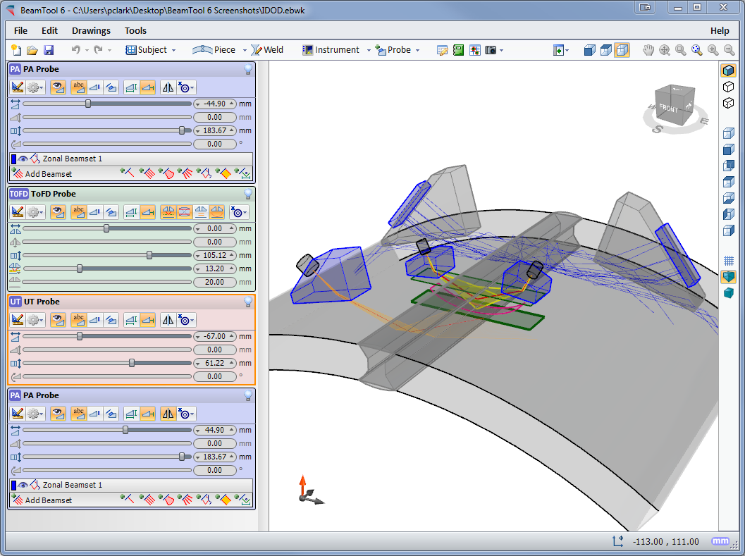
BeamTool now supports tracing sound paths in 3 dimensions.
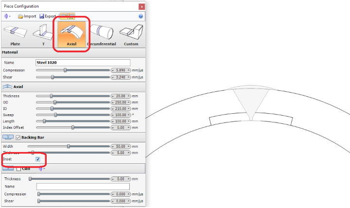
The backing bar can be inset, and is now available for Axial pieces.
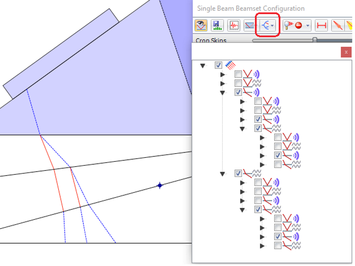
It is now possible to customize which sound modes are displayed at each interface reflection/refraction. This can help when the various sound modes become too cluttered.
A J bevel can be created in root to create a double J weld bevel.
When the transverse angle is not zero, beamset measurements can be calculated from multiple points of view (view planes).
BeamTool was designed to meet the modern operator's need for speed. Phased array technique development is more complex than that for conventional ultrasonic inspection and as such requires effective tools to help define the inspection approach.
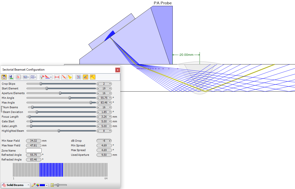
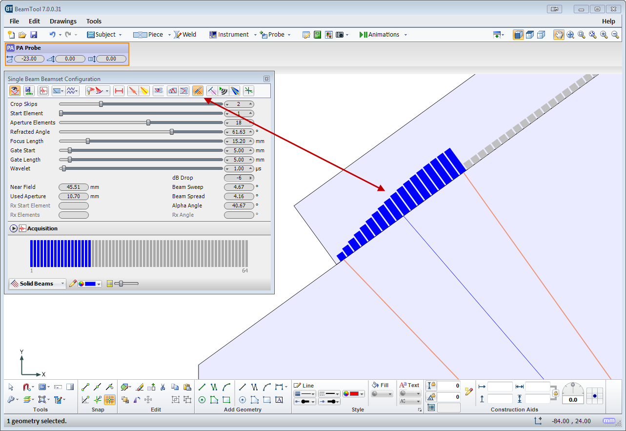
BeamTool's innovative approach to phased array enables linear, sectorial and an informative reference cursor option to be represented, helping to clearly convey weld coverage, HAZ coverage and probe position, in addition to critical dimensions. The beamset parameters dialog displays a visual representation of the transducer elements that are used to form the beamset.
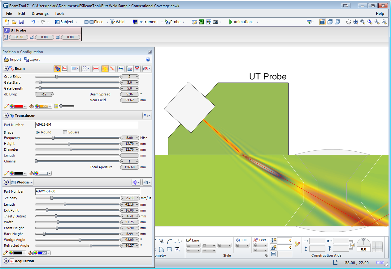
Beam spread visualization allows you to more accurately see your beamset coverage for a specific dB drop, and near field visualization ensures that any focusing being performed is within the near field. True Depth, Projection and Half Path focus types can be visualized in your workspace and documented in your technique report.
Conventional probes can also be modeled in BeamTool with advanced support for beam spread and near field rendering.
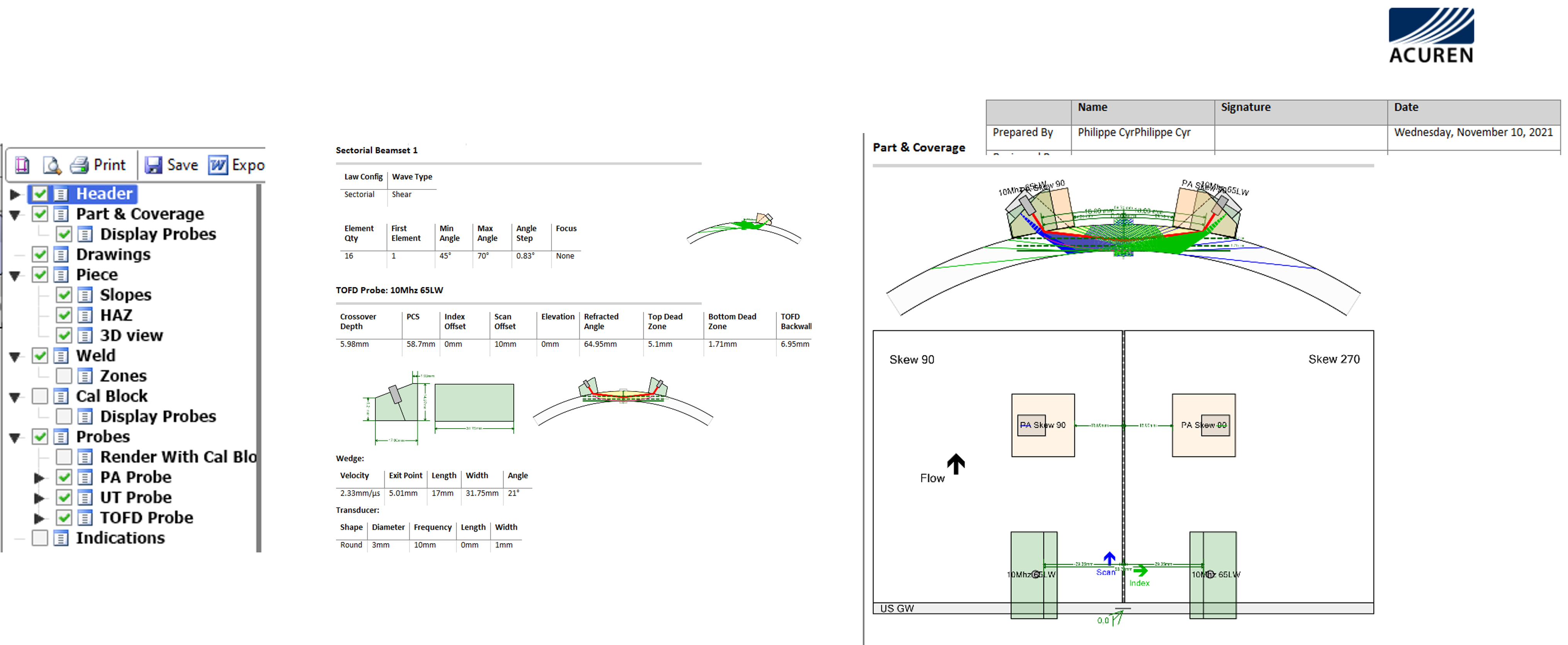
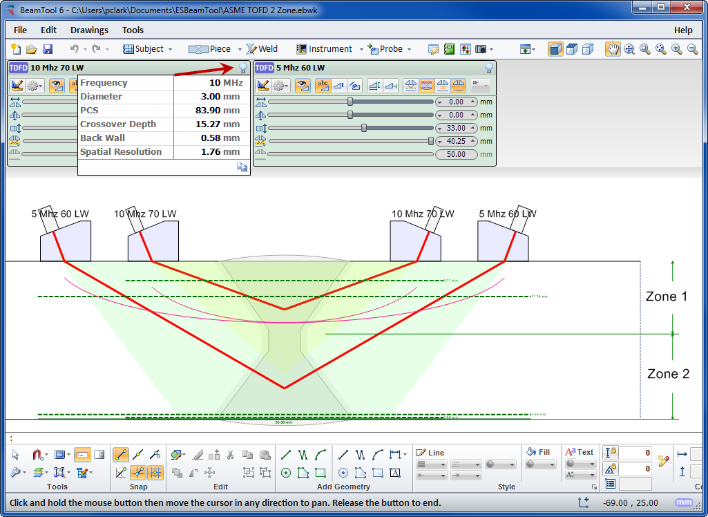
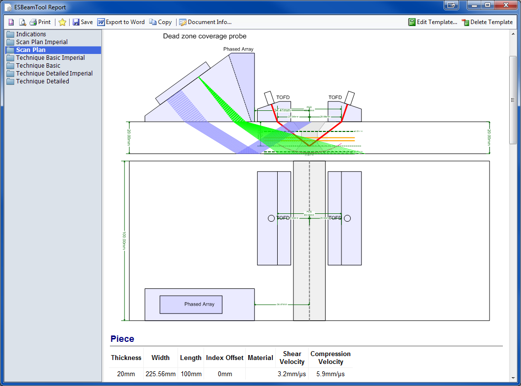
Time-Of-Flight Diffraction support provides tools to visualize and confirm zonal coverage. TOFD techniques can be automatically annotated with cross-over dimensions and dead-zone depiction. Effortlessly define Probe Center Separation (PCS) by selecting the cross-over depth you want and BeamTool automatically positions the probes to target your requirements.
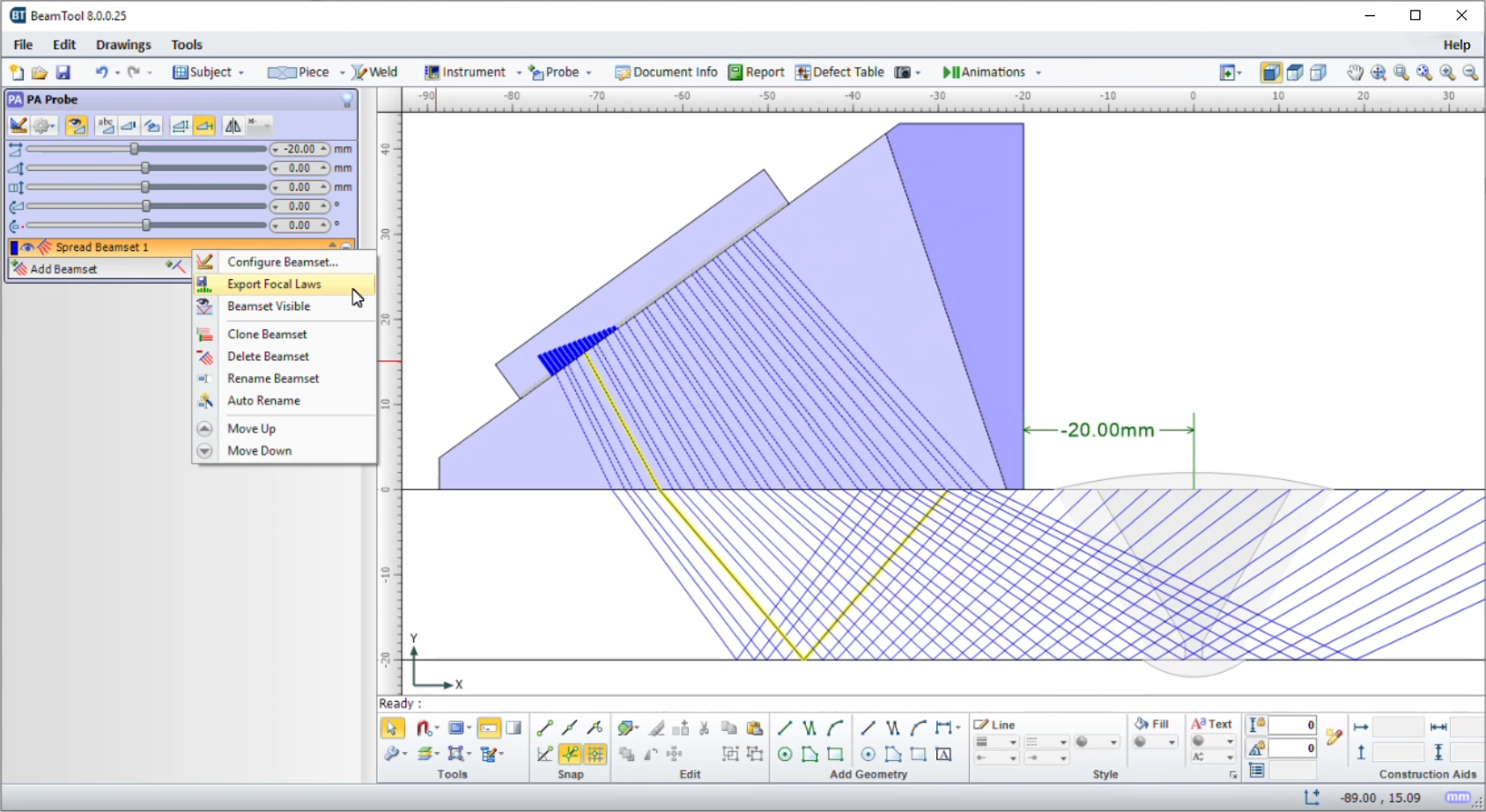
Export Focal Laws
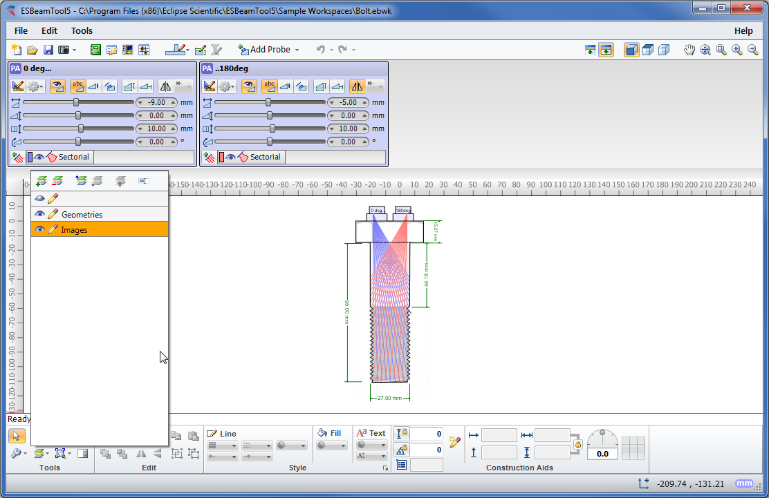
The Export Focal Laws feature added in BeamTool 7 helps users directly import their optimized scan plan into a phased array instrument. Before an inspection, BeamTool helps design phased array inspection plans by laying out the inspection methodology. Potential scanning configurations are modeled and beam directions are identified to ensure full coverage of the desired location is achieved. Once the scanning parameters have been finalized through the scan plan, BeamTool’s focal law calculator calculates the appropriate time delay for excitation of each active array element (focal law) for generation of beams with the specified refraction angles. The calculated focal laws as well as wedge delays are listed in law a file. The law file can be exported from BeamTool 7 and directly imported into a phased array instrument. This allows for immediate inspection with no need for further adjustment in the instrument.
High temperature law files generated with the BeamTool HighTemp Add-on can be used along with high temperature wedges to facilitate phased array inspections at elevated temperatures. This ensures technicians will perform accurate inspection with compensations of temperatures effects on the scan results, leading to accurate indication detection and positioning at elevated temperatures.
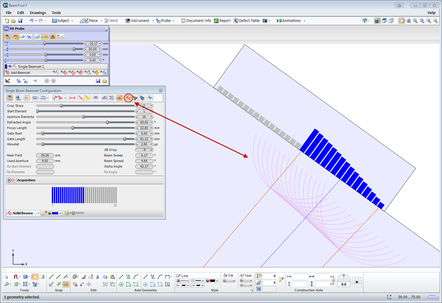
Focal Delay Visualization
The Show Elements option for Single Beam Beamsets will now live reflect the focal delays as beam parameters are modified.
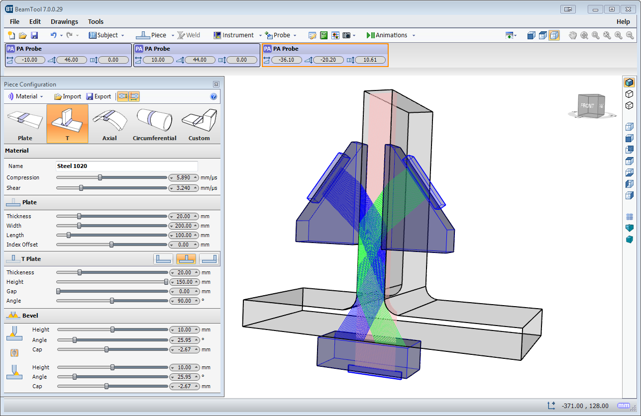
Improved and simplified way to configure L and T shape welded components from an easy to use, configurable menu.
Sound Propagation Animation shows how elements firing in a phased array probe constructively form a wave front and how that wave front propagates into the piece.
Indication drawing sets can now be added to the workspace

Allows users to easily scale images and geometries to precise measurements.
A powerful educational tool for rendering sound pressure at any point in the field represented by a geometric or bitmap wavefront. Using real field physics the wavefront can be focused, and even steered, by adding a time
Displays the wavelets for each individual element at a selected time in micro seconds (Single Beamset only).
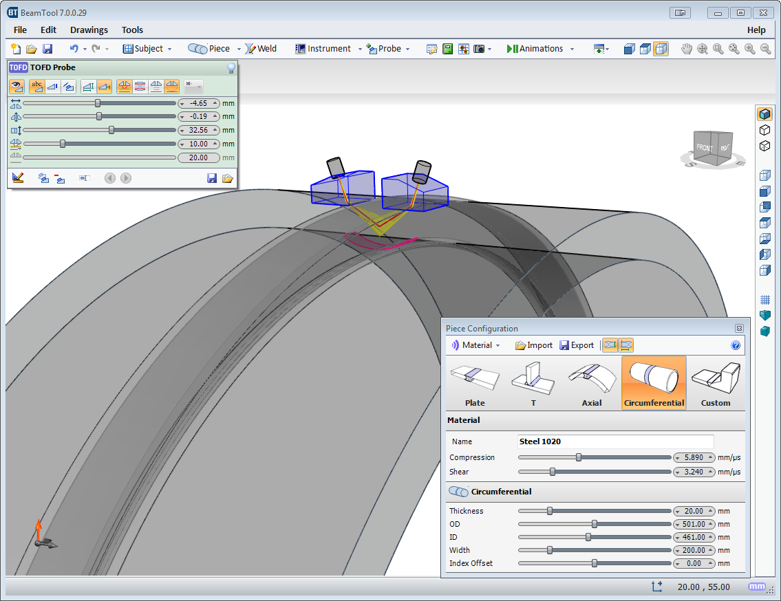
Circumferential pieces are now properly represented in 3D View.
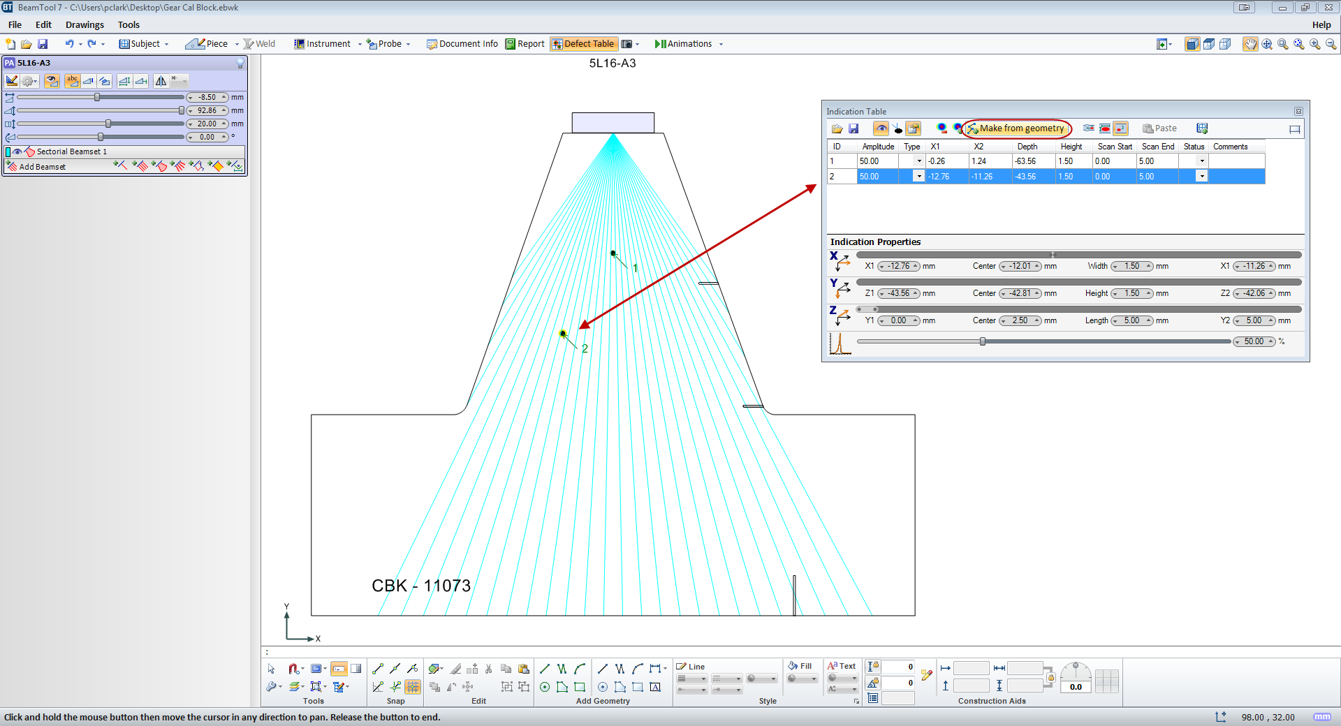
Indications can now be added to the indication table from any selected geometry in the workspace.
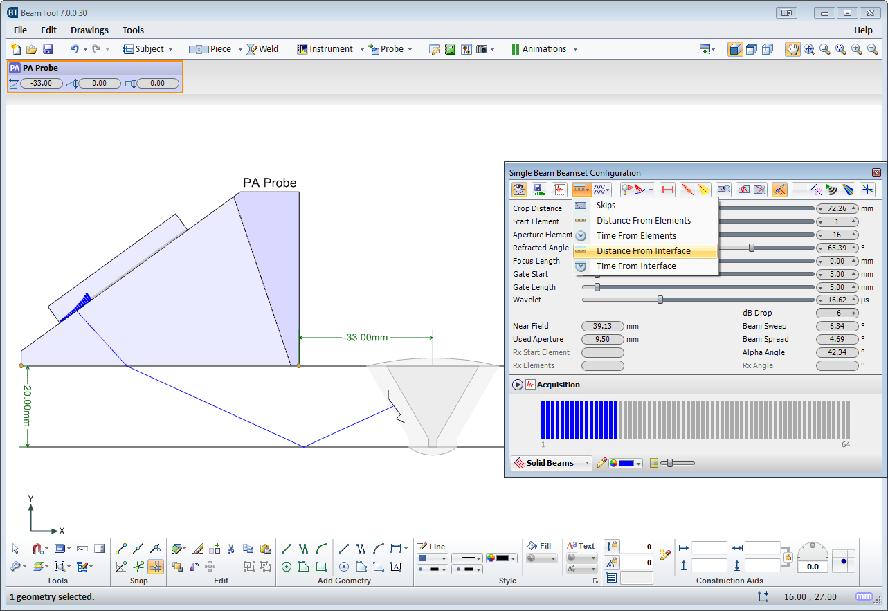
Identify any type of point on a beam path based on Distance from Elements, Time from Elements, Distance from Interface, Time from Interface or Skips.
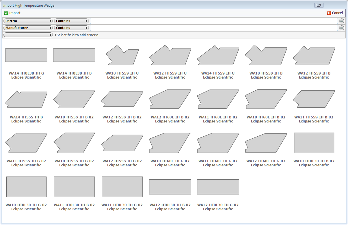
The catalog for the High Temp Add-on has been populated with several new Eclipse Scientific HighTemp wedges.
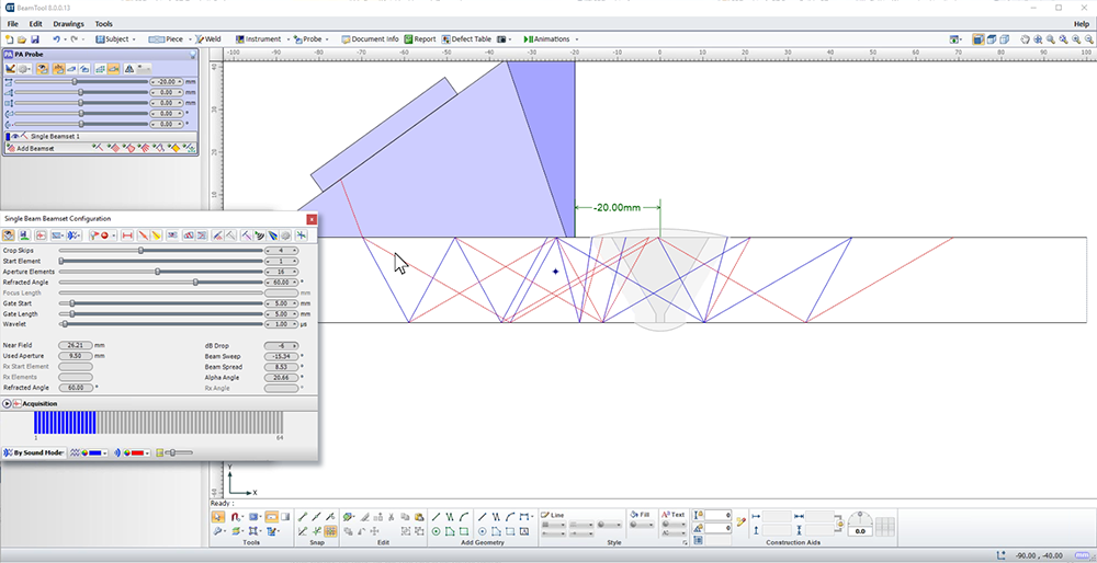
Techniques can be created using multiple probes and multiple disciplines within a single workspace. Combine Phased Array with Conventional UT and TOFD probe configurations to ensure complete coverage. Pitch-catch is a useful technique for viewing unfavourable weld bevels or targeting geometry. Simply select P/C in the phased array configuration and the BeamTool will solve and present the elements required; this feature can be set to reflect off the weld bevel face accounting for return refraction.
BeamTool makes it easy to develop pitch-catch techniques for direct and indirect inspection using a single probe or a pair of probes.
The 3D view will display your piece, annotations, probes and beams in an interactive viewing environment. Rotation, Panning and Zooming tools; Mesh, Solid and Surface modeling modes; and Perspective and Orthographic projection modes all provide a powerful, intuitive, highly interactive modeling tool for visualizing your techniques like never before. And along with the new "Construct Top View" tool, simple custom-drawn pieces can quickly be given depth and viewed in 3D as well.
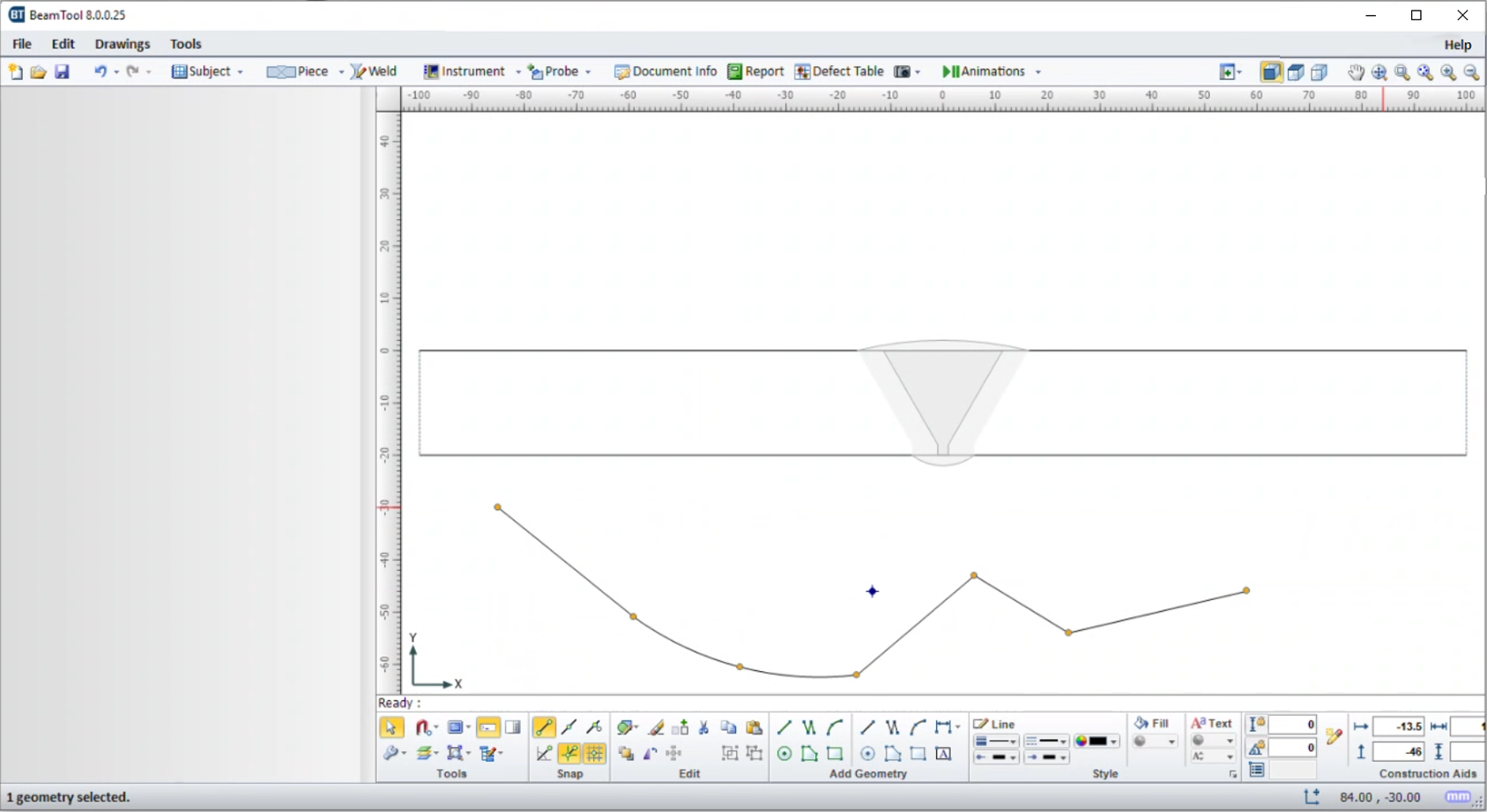
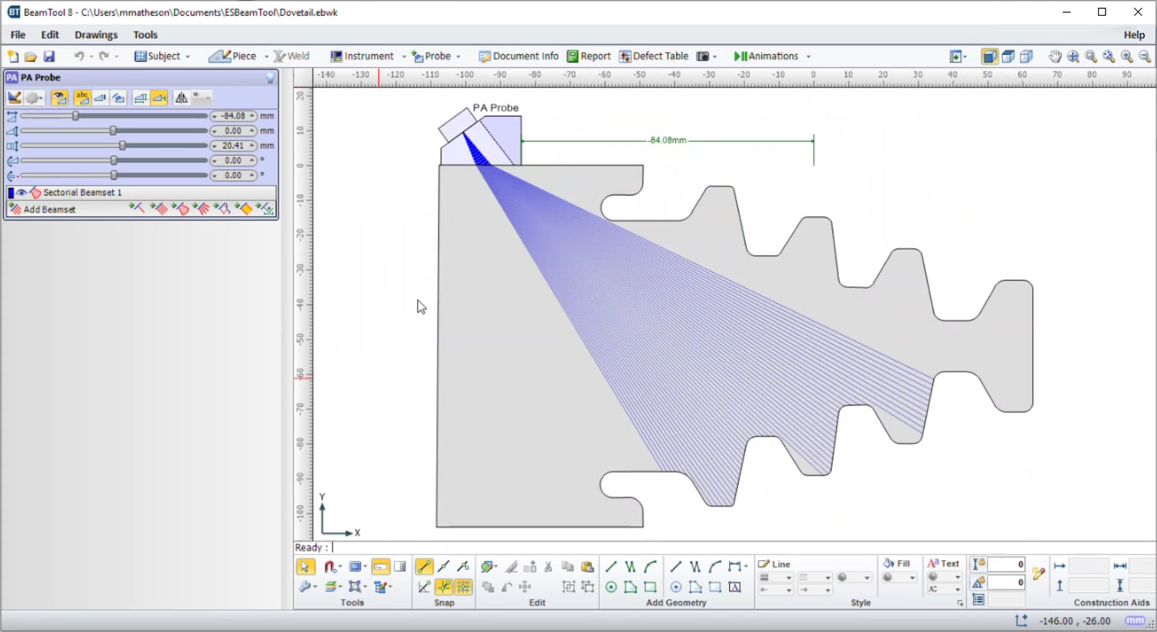
BeamTool integrates a powerful set of CAD tools that makes it easy to draw custom pieces to develop a scan plan for your inspection. Users can draw geometries of any shape and size and use the advanced ray tracing to accurately ensure and document proper coverage. The drawing tools have been greatly enhanced to make it even easier to draw and edit. Precision coordinate and size readout, along with the ability to snap and a Command Prompt for making complex specimen drawing precise, fast and easy. Multiple layers can be created to organize and filter your geometries.
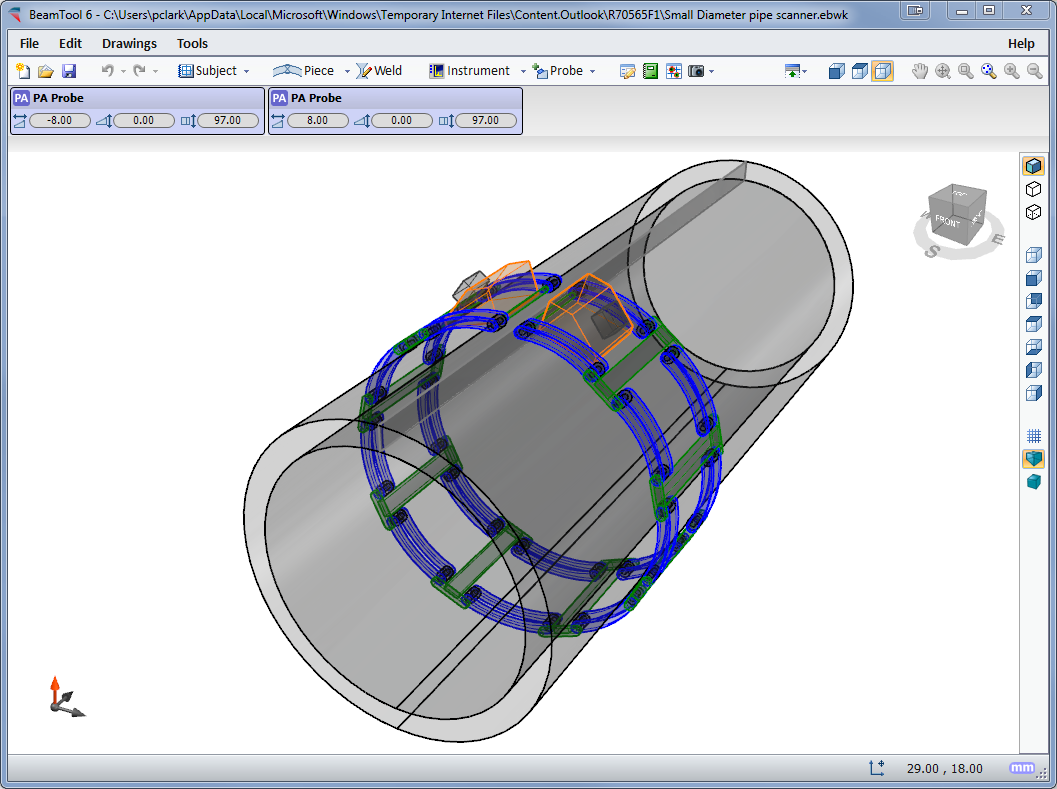
BeamTool provides native support for ID/OD type pieces common in pipeline and boilers. The piece editor allows the piece to be easily defined using the OD and ID or thickness of a part. Once the part is configured, phased array and conventional probes can be pinned to the outside or inside of the part. As the user adjusts the probe location, the probe stays pinned to the part and revolves around it.
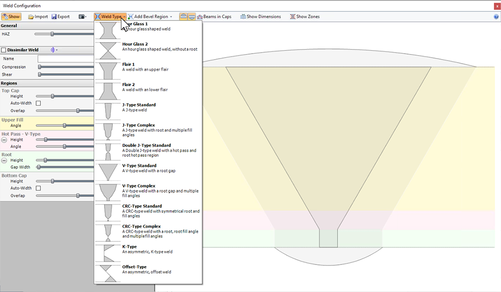
Pick from a list of standard weld configurations or use the advanced weld configuration editor to accurately create any weld profile you require. Weld cap geometries allow you to clearly illustrate how close you can get your probe to a weld while ensuring proper coverage.
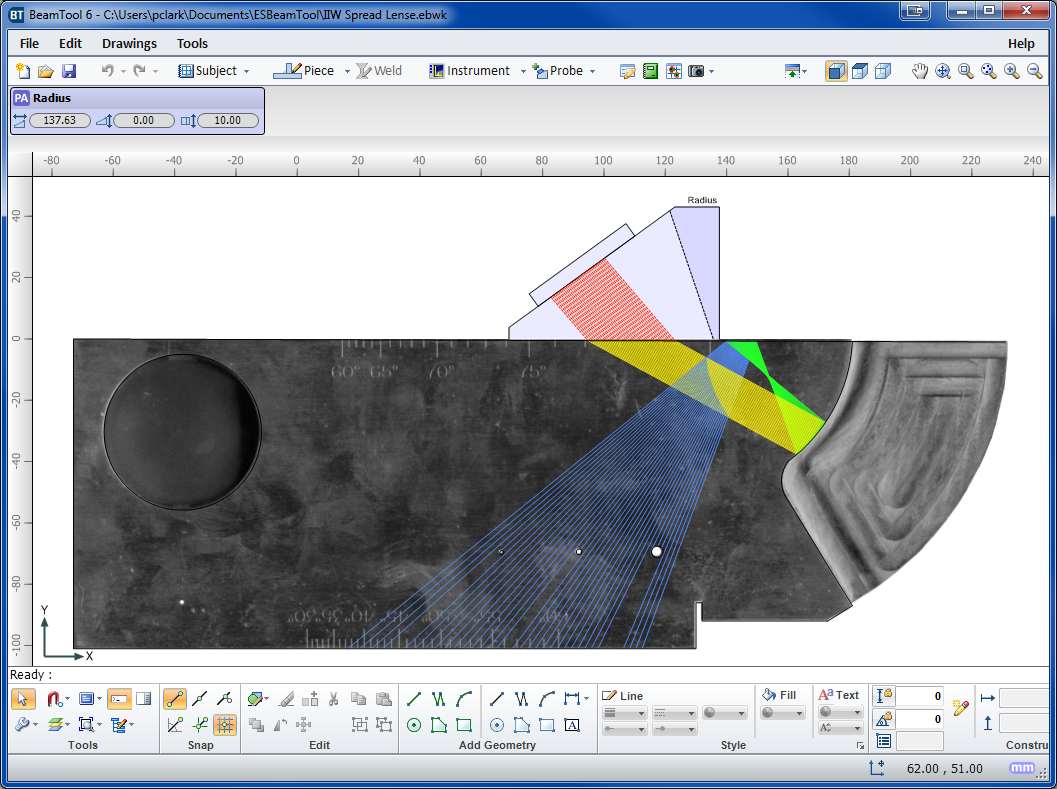
Use the bitmap drawing tool to add images to your drawings. Bitmaps can be imported and scaled to be used as a backdrop or to use as a reference to trace over when drawing complex specimens.
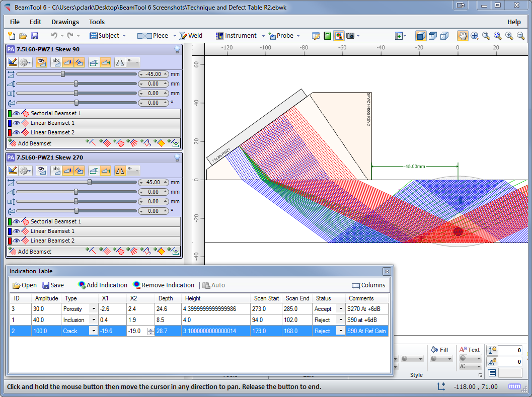
Defects/Indications can be entered into a table defining their spatial coordinates, then visualized on the workspace in 3D space. The amplitude of defects is visualized through a colored palettizer.
HTML standards-based reporting allows reports to be generated and shared across the web or email. Report content can be copied into other programs, such as Microsoft Word, and edited for final presentation. Users can easily customize or create new reports containing the information they need. The built-in HTML editor allows reports to be constructed in an environment similar to a common word processor. Workspace fields can be dragged from a field picker into the template for inclusion in the report.
This versatile tool simplifies the technique design, validation and reporting process and is adaptable for use by engineers, technicians, and auditors. If you are dealing with ultrasonic inspections and require the ability to visualize and document the applications, BeamTool will guide you through the process and produce the professional results industry demands.
BeamTool ZONAL Add-on provides the ability to define Weld Zones, which are used in conjunction with a Zonal Beamset to provide automated targeting of individual phased array beams into specific locations along the face of a weld bevel. The powerful new Beam Solver will then optimize the Focal Laws.

For more information, email us at esbeamtool@eclipsescientific.com
or call (519) 372-1831 and ask for BeamTool Support
![]()